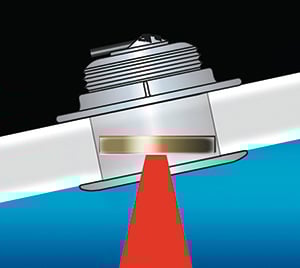
This SS175 is a stainless steel semi-flush mushroom thru-hull. It has a tilted element, so it is compatible with hull deadrises from 8° to 15°. All images and diagrams in this article courtesy of Airmar Technologies, the leading manufacturer of recreational fishfinder transducers.
A thru-hull transducer installation is the most capable and most permanent way to mount a fishfinder transducer — and the most demanding DIY project in that category. Unlike a transom-mount or in-hull transducer, a thru-hull requires drilling a hole through the bottom of the boat below the waterline and creating a watertight, permanently bedded mounting. Done correctly, a thru-hull delivers the best sonar signal quality of any mounting method because the transducer face is in direct, undisturbed contact with the water at all times. Done incorrectly, it can create a leak that slowly floods your bilge — or a fast one.
This guide covers the complete installation process: transducer selection by hull material, mounting location selection by hull type, tools and hole saw sizing, fairing block fabrication, bedding and installation, cored hull treatment, cable routing, and leak checking. Schedule this work during a haulout for winter layup, bottom paint application, or other planned maintenance — you will need the boat out of the water for the drilling, bedding, and installation steps, and it should remain out until the sealant has fully cured.
Before the scheduled haulout, confirm you have the correct transducer. The transducer must be compatible with your fishfinder's connector and sonar frequencies, and compatible with your hull material. The material matching rules are specific and not interchangeable:
- Bronze transducers: recommended for fiberglass or wood hulls
- Plastic transducers: recommended for fiberglass or metal hulls; not recommended for wood hulls, where wood expansion can crack plastic
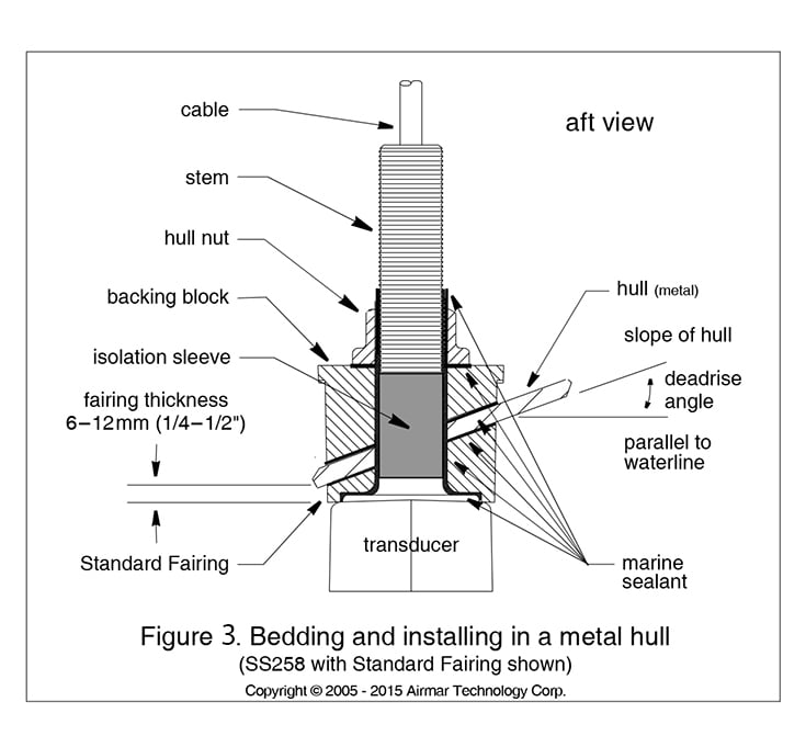
- Stainless steel transducers: recommended for steel or aluminum hulls; when installing stainless into an aluminum or steel hull, the transducer must be electrically isolated from the hull using the isolation sleeve provided, to prevent galvanic corrosion between dissimilar metals
If you have questions about transducer compatibility with your specific fishfinder and hull, call 1-800-BOATING or discuss transducer selection with a West Marine store associate before purchasing.
Mounting Location Guidelines
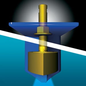
B260 bronze thru-hull with standard fairing block. It is cut at the angle of the hull's deadrise, and part of the fairing is mounted inside the hull as a backing plate.
Transducer location is the single most important variable in a thru-hull installation — a correctly selected and bedded transducer in the wrong location will still produce poor sonar performance. The fundamental requirement is that the transducer face must be in contact with smooth, undisturbed water at all speeds and conditions where you intend to use the fishfinder. Turbulence, air bubbles, and acoustic interference from propellers and machinery all degrade sonar signal quality and can make a correctly installed transducer appear to fail.
Do not mount the transducer in line with or near the engine water intake, discharge openings, or behind strakes, struts, fittings, or hull irregularities that will disturb water flow. Do not mount it where the boat is supported during trailering, launching, hauling, or storage.
- The water flowing under the hull must be smooth with a minimum of bubbles and turbulence, especially at high speeds.
- The transducer must be continuously immersed in water — on a planing hull, this means positioning it where it remains wetted at cruise speed and above.
- The transducer beam must be unobstructed by the keel or propeller shaft(s).
- Choose a location away from interference caused by propellers and shafts, machinery, other depth sounders, and other cables. Lower background noise permits higher fishfinder gain settings and better target resolution.
- Choose a location with minimal deadrise angle, unless you are installing an appropriate tilted-element transducer designed for your hull's specific deadrise range.
- Choose an accessible spot inside the vessel with adequate clearance for the height of the transducer stem and room to get a large wrench around the hull nut during tightening.
- CHIRP transducers must be mounted in a cool, well-ventilated area away from the engine to avoid overheating the transducer electronics.
- For displacement hull powerboats: locate the transducer 1/3 of the way along the LWL and 6” to 12” off the centerline.
- For planing hull powerboats: mount it well aft near the centerline, well inboard of the first set of lifting strakes to ensure contact with water at high speeds. The starboard side where the propeller blades are moving downward provides a cleaner water flow.
- For outboards and I/Os: mount it just forward and to the side of the engine(s).
- For inboards: mount it well ahead of the propeller(s) and shaft(s).
- For stepped hulls: mount it just ahead of the first step.
- For boats capable of speeds above 25 knots: review transducer location and operating results of similar boats before proceeding — at high speed, turbulence and ventilation are more critical variables.
- For fin keel sailboats: mount it to the side of the centerline, forward of the fin keel 1’ to 2’.
- For full keel sailboats: locate the transducer amidships, away from the keel, at the point of minimum deadrise angle.
Boat Types
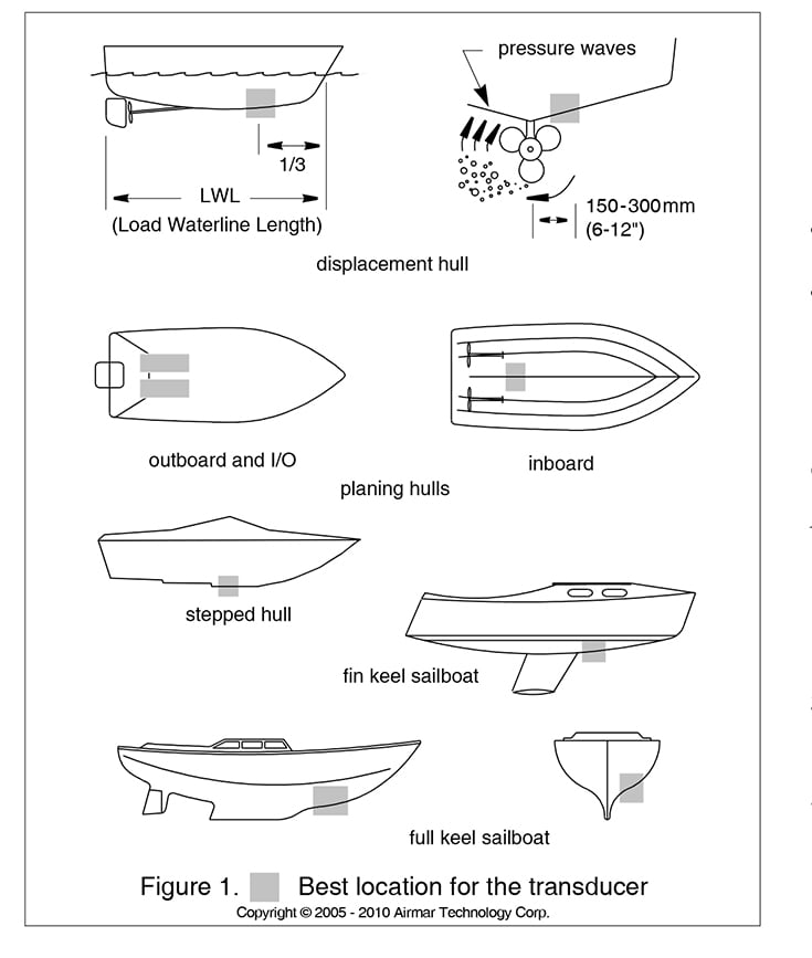
The diagram above shows the recommended transducer mounting zones for the most common hull types. The key principle in each case is the same: find the area of smoothest, most consistent water flow under the hull at the boat’s normal operating speeds. On planing hulls, this means the aft section inboard of the lifting strakes. On displacement hulls and sailboats, this means forward of the propeller and keel appendages. On stepped hulls, the area just ahead of the first step provides the most consistent water contact across speed ranges.
Do You Need a Fairing Block?
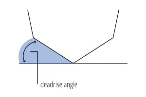
A fairing block is a wedge-shaped piece that corrects for hull deadrise — the angle the hull makes with the horizontal — so the transducer face is parallel to the water surface rather than angled with the hull. Whether you need one depends on the combination of your hull’s deadrise angle at the mounting location and the transducer you are installing.
Some Airmar transducers include a tilted element — the ceramic transducer inside is already offset from perpendicular to the housing face — and are designed for installation in hulls with a specific deadrise range without a fairing block. For example, the SS175 shown at the top of this article is designed for hulls with 8° to 15° deadrise. If your hull’s deadrise at the mounting location is within the transducer’s designed range, no fairing is required. If the hull deadrise is outside that range, or if the transducer does not have a tilted element, a fairing block must be fabricated and used. When in doubt, use a fairing — a transducer installed at even a moderate angle produces an off-axis beam that misses bottom and fish targets that would be visible with a correctly aimed transducer.
Special Considerations for Cored Fiberglass Hulls
Cored fiberglass hulls — hulls with a foam, balsa, or other lightweight core sandwiched between inner and outer fiberglass skins — require additional preparation before the transducer is installed. A thru-hull fitting installed directly through a cored hull will compress the core when the hull nut is tightened, which can delaminate the hull structure around the fitting. More critically, the core material is permeable: water that contacts it through any gap in the sealant will wick outward through the core over months and years, eventually causing widespread delamination that is far more expensive to repair than the original installation.
The correct procedure is to remove the core material from around the hole and replace it with solid fiberglass or epoxy before installing the transducer. Drill the through-hole at the larger diameter specified for cored hulls (see the Tools and Materials section below for model-specific sizing). Using a router, drill, or sharp tool, carefully excavate the core material from inside the hole to a diameter slightly larger than the transducer stem — typically 35mm to 42mm depending on the transducer model — and to the full thickness of the core. Fill the excavated area with thickened epoxy, inserting a cylinder of the correct diameter to maintain the hole while the epoxy cures. Once fully cured, remove the cylinder and proceed with the standard installation procedure. The epoxy plug isolates the core from any water contact and provides a solid, incompressible surface for the hull nut to bear against.
Tools and Materials
- Safety goggles
- Dust mask
- Electric drill
- Drill bits and hole saws for some typical Airmar thru-hulls (Pilot hole: 6mm or 1/4”); For Airmar B45, SS505 transducers: 22mm or 7/8”; For Airmar B258, B271W, B285HW, B285M, SS258 transducers: 30mm or 1-3/16”; For Airmar B260, B265LH, B265LM, B275LHW, SS260, SS270W transducers: 33mm or 1-5/16”
- Sandpaper
- Mild household detergent or weak solvent (such as alcohol)
- File (for installation in a metal hull)
- Angle finder bevel gauge (for installation with a fairing block)
- Bandsaw or table saw (for installation with a fairing block)
- Rasp or power tool (for installation with a fairing block)
- Marine sealant suitable for below-waterline use (3M 4200 or Sikaflex 291)
- Slip-joint pliers
- Grommet(s) for cable chafe protection at bulkheads
- Cable ties
Drill bits, hole saws and materials for installation in a cored fiberglass hull:
- For Airmar B45, SS505 transducers: 35mm or 1 3/8”; For Airmar B258, B271W, SS258, B285HW, B285M transducers: 40mm, 41mm, or 1 5/8”; For Airmar B260, B265LH, B265LM, B275LHW, SS260, SS270W transducers: 42mm or 1 5/8”
- Cylinder, wax, tape, and casting epoxy (for cored hull core replacement)
Installation: No Fairing Block or Standard Fairing Only
- Drill a 6mm or 1/4” pilot hole perpendicular to the waterline from inside the hull. If there is a rib, strut, or other hull irregularity near the selected mounting location, drill from the outside instead.
- Using the appropriate size hole saw, cut the full-size hole from outside the hull. Hold the drill so the hole will be perpendicular to the water’s surface. Start the drill in reverse to score the gelcoat surface — this prevents chipping and gives a cleaner edge. Then proceed forward to complete the cut.
- Sand and clean the area around the hole, inside and outside, to ensure the marine sealant will adhere properly. Remove any petroleum residue with mild household detergent or weak solvent (alcohol) before sanding. For a metal hull, remove all burrs with a file and sandpaper.
- Tape off the hull with blue #2090 masking tape. Dry-fit the transducer and trace the outline of the mushroom or football-shaped head on the tape. Use a utility knife to cut out that shape from the tape. This step makes cleanup of the squeezed-out sealant much easier after the hull nut is tightened.
Cutting the Standard Fairing Block
A fairing block is required whenever the hull deadrise at the mounting location is outside the designed range of the transducer’s tilted element, or when the transducer has no tilted element. The fairing is cut from the piece that came with the transducer (or sourced separately for the specific transducer model) and must be cut to precisely match the hull deadrise at the mounting location. An incorrectly angled fairing is worse than no fairing — it tilts the transducer away from vertical rather than correcting for the hull angle.
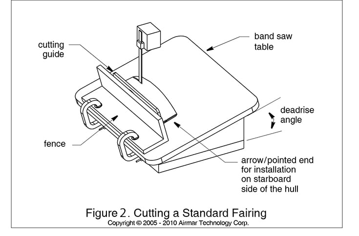
You will need a bevel gauge to measure the deadrise angle and a bandsaw or table saw to make the angle cut. CAUTION: woodworking machinery, especially table saws, can cause serious injury. If you are not experienced with these tools, have a qualified woodworker make the fairing cut, or choose a different mounting approach.
The arrow or pointed end of the fairing points forward toward the bow. Be sure to orient the fairing correctly for the side of the hull on which it will be installed — a fairing cut for the starboard side is the mirror image of one cut for the port side.
- Measure the deadrise angle of the hull at the selected location (see diagram at right).
- Tilt the bandsaw table to the measured angle and secure the cutting fence.
- Place the fairing on the table so the cutting jig rests against the fence. The arrow/pointed end will face toward you for starboard installation or away from you for port installation.
- Adjust the cutting fence so the fairing will be cut in approximately two equal parts. The section that becomes the exterior fairing must be between 1/4” and 1/2” at its thinnest dimension.
- Recheck steps 1 through 4, then cut the fairing.
- Shape the fairing to the hull as precisely as possible with a rasp or power tool — any gap between the fairing and the hull surface will be filled by sealant, but a close fit reduces the amount of sealant required and provides a more secure mechanical bond.
- Use the remaining section of the fairing attached to the cutting jig as the backing block that installs inside the hull.
Bedding the Transducer
CAUTION: All surfaces to be bedded must be clean, dry, and free from any contamination. Sealant applied over oil, wax, or damp surfaces will not bond and will fail. If the hull was recently antifouled, verify that the antifouling paint at the mounting location has been sanded away down to bare hull material — sealant does not bond reliably to antifouling paint.
- Remove the hull nut from the transducer stem.
- Thread the transducer cable through the fairing if one is being used.
- Apply a 1/16” thick layer of marine sealant (3M 4200 or Sikaflex 291 are the appropriate choices for below-waterline use — do not use standard silicone, which is not rated for permanent underwater contact) to the surface of the transducer that will contact the hull or fairing, and up the stem. The sealant must extend 1/4” higher than the combined thickness of the hull, fairing, backing block if used, and hull nut. This ensures sealant is present in the threads to create a watertight seal and to lock the hull nut. For a stainless steel transducer installed in a metal hull, slide the isolation sleeve over the bedded transducer stem as far down as possible. Apply a 1/16” layer of sealant to the outside of the sleeve.
- Apply a 1/16” layer of sealant to the fairing surface that contacts the hull, to the backing block surface that contacts the hull interior, and to the hull nut face that contacts the backing block.
- For a standard fairing: seat the transducer firmly in and against the fairing with a pushing, twisting motion. Confirm the locating button on the fairing mates with the recess in the transducer housing — this button ensures correct orientation and prevents the fairing from rotating.
Installing the Transducer
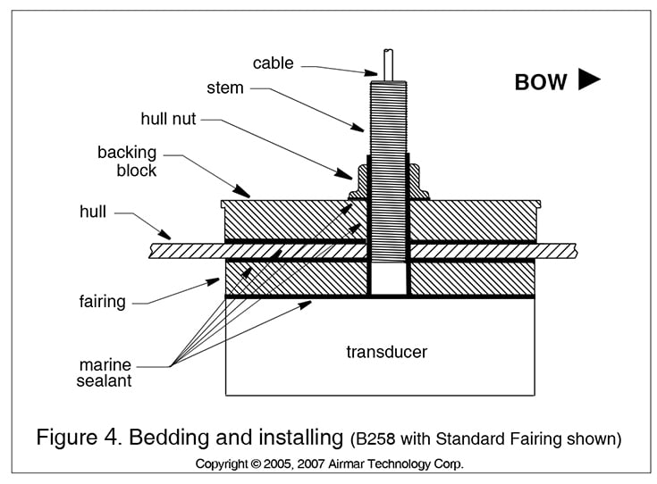
- From outside the hull, thread the cable through the mounting hole. Push the stem of the transducer through the hole with a twisting motion to distribute and squeeze out excess sealant evenly. Align the transducer so the blunt or button or arrow end faces forward toward the bow, with the long axis parallel to the centerline. For a stainless steel transducer in a metal hull, confirm the isolation sleeve is between the transducer stem and the hull, but positioned below the hull nut so it does not interfere with tightening.
- From inside the hull, slide the backing block (if using a fairing) and then the hull nut onto the cable. Seat the backing block against the hull with the arrow end facing forward. Screw the hull nut onto the transducer stem and tighten with slip-joint pliers until snug and secure. For cored fiberglass hulls, do not overtighten — you are threading into the epoxy fill, not solid laminate, and crushing the core around the fitting is a common and difficult-to-repair mistake. For wood hulls, leave the nut slightly loose to allow for wood swelling before final tightening after the hull has been in the water.
- Remove all excess marine sealant from the outside of the hull and fairing surface to ensure smooth, undisturbed water flow across the transducer face. Any sealant bead or ridge on the downstream side of the transducer creates turbulence that degrades sonar performance.
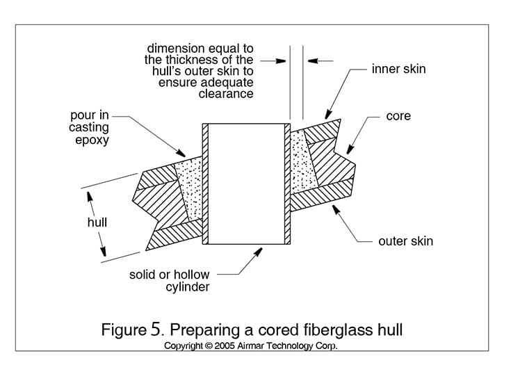
Installation in a cored fiberglass hull requires removal and replacement of the core material in the area of the fitting. In the diagram above, the core has been replaced with epoxy and a correctly sized cylinder glued inside to maintain the hole during curing. The epoxy fill prevents water ingress into the core and provides a solid, compressible-resistant surface for the hull nut.
Cable Routing and Connecting
If the transducer includes a waterproof connector, do not remove it to ease cable routing. If the cable absolutely must be cut and spliced — for example, if it is too short for the routing path — use Airmar’s splash-proof Junction Box (33-035, available by Special Order) and follow the supplied instructions precisely. Removing the waterproof connector or cutting the cable without using an approved watertight junction box voids the transducer warranty and leaves the cable jacket splice exposed to bilge moisture, which will cause signal degradation and eventual electrical failure.
- Route the cable to the fishfinder carefully, avoiding sharp bends, pinch points at bulkheads, and contact with hot engine surfaces. Use grommets at every bulkhead penetration to prevent chafing of the cable jacket. Support the cable with cable clamps or wire ties per ABYC marine wiring standards. Separate the transducer cable from other electrical wiring and the engine by at least 6 inches where possible — parallel runs near power cables introduce electrical interference that appears as noise on the sonar display. Coil any excess cable and secure it with cable ties away from moving parts and heat sources.
- Connect the transducer to the fishfinder per the fishfinder owner’s manual. Most modern Airmar transducers use a keyed connector that can only be inserted in one orientation — do not force the connector if it does not seat easily, as forcing a misaligned connector damages the pins.
Check for Leaks
When the boat is placed in the water, go below immediately and check the area around the transducer stem and hull nut for any water intrusion. Pay attention to the threads above the hull nut and the joint between the fairing and hull surface outside — both are common locations for small seeps. Very small leaks may not be immediately visible as dripping water; look for wet surfaces or moisture beading on the hull interior around the fitting.
Do not leave the boat unattended in the water for more than three hours on the first day without rechecking. A slow leak that is invisible in the first hour can produce significant bilge accumulation over 24 hours — far more than the bilge pump can handle if the boat is left overnight. If any leak is observed, haul the boat, allow the sealant to cure, remove the transducer, clean all surfaces, and repeat the bedding and installation procedure completely. Attempting to seal a leaking thru-hull from inside while the boat is in the water is not reliable.
Frequently Asked Questions: Thru-Hull Transducer Installation
When should I choose a thru-hull transducer over a transom-mount?
A thru-hull transducer delivers better sonar performance than a transom-mount in most conditions because the transducer face is in direct, undisturbed contact with the water below the hull rather than hanging behind the transom in propeller wash and hull turbulence. Thru-hull installations are the standard choice for displacement hull powerboats, sailboats, and any boat where the owner wants maximum sonar performance and doesn’t mind the more involved installation. Transom-mount transducers are simpler to install and easier to replace, and are adequate for most recreational fishing applications on planing powerboats. If your boat already has a thru-hull fitting from a previous transducer, replacing it with a new thru-hull is often the most practical choice.
Do I need a fairing block for my thru-hull installation?
It depends on your hull’s deadrise angle at the mounting location and whether your transducer has a tilted element. Some Airmar transducers include a tilted ceramic element that compensates for a specific deadrise range — if your hull’s deadrise falls within that range, no fairing is needed. For hulls with deadrise outside the transducer’s designed range, or for transducers without a tilted element, a fairing block must be fabricated to angle the transducer face parallel to the water surface. Measure your hull deadrise with a bevel gauge at the planned mounting location before purchasing the transducer, and check the transducer’s specifications to determine whether a fairing is required.
What sealant should I use for a thru-hull transducer?
Use a marine sealant rated for permanent below-waterline use — 3M 4200 or Sikaflex 291 are the standard choices for thru-hull transducer installations. Do not use standard silicone, which is not rated for continuous water immersion. Do not use 3M 5200 for this application — 5200 is a permanent adhesive sealant that makes future removal of the transducer extremely difficult without damaging the hull. 4200 and Sikaflex 291 cure to a firm, flexible seal that holds securely and allows future removal with reasonable effort.
How do I install a thru-hull transducer in a cored fiberglass hull?
Cored hulls require removing the core material from around the hole and replacing it with solid epoxy before installing the transducer. Drill the hole at the larger diameter specified for cored hulls, excavate the core to a diameter slightly larger than the transducer stem, fill the excavated area with casting epoxy using a correctly sized cylinder to maintain the hole during curing, allow the epoxy to fully cure, then proceed with the standard bedding and installation procedure. This prevents water from entering the core material and prevents the hull nut from crushing the core laminate when tightened.
Can I cut the transducer cable to make routing easier?
Only if you use Airmar’s splash-proof Junction Box (part number 33-035, available by Special Order) and follow its included instructions. Cutting the cable without using an approved watertight junction box voids the transducer warranty and leaves the splice exposed to bilge moisture, causing signal degradation and eventual failure. If the cable is too short for your routing path, plan for a junction box location during installation rather than attempting a field splice.
Browse All Marine Electronics & Navigation Gear
- Chartplotters, GPS units, radar systems, and integrated navigation displays
- Sonar, CHIRP, downscan, and fish-finding electronics
- Marine stereos, speakers, amplifiers, and audio accessories
- VHF radios, AIS, satellite communication equipment
- Autopilot systems and steering control components
- Wind, depth, speed, and multifunction instruments
- Marine binoculars for navigation and low-light use
- Thermal and night-vision devices for situational awareness
- Onboard monitoring and security systems
- Magnetic and electronic compasses
- Paper and electronic navigation charts
- Regional cruising and harbor guides
- Traditional navigation plotting tools