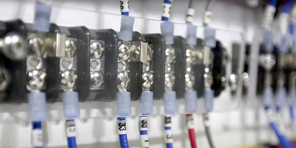

Marine grade wire is manufactured in multiple gauges for different applications. Use the charts below to determine the correct wire gauge, based on the amount of current in the circuit and the length of the wire run.
Even the experts have to check occasionally on the correct gauge and ampacity (maximum amount of electrical current a conductor can carry) of wire for a given marine DC load. The simplest method we’ve found uses the charts below.
- Select either the 10% or 3% voltage drop chart, based on the type of load you are running.
- Find the current consumption of the load on the horizontal axis of the chart.
- Find the length of the circuit on the vertical axis of the chart, noting that the length is the round-trip distance from the panel or battery to the load and back.
- The wire size listed in the graph at the intersection denotes the gauge of wire to use.
We’ve included copper wire specifications which comply with the AWG standards at the bottom.
Of particular interest is the equation:
Voltage Drop = Current x Length x Ohms per foot
This simple equation allows you to calculate the voltage drop for a circuit of any length and any current flow, if you know the resistance of the wire.
Finally, note that the amp capacity (ampacity) of the wire curtails using very short lengths of wire for large current flows, as shown by the “flat tops” of the 10% chart areas.
These graphs assume:
- 105°C insulation rating: All Ancor wire uses 105°C insulation rating. Lower temperature insulation cannot handle as much current
- AWG wire sizes, not SAE: All Ancor wire uses AWG wire sizes. SAE wire sizes are 6 to 12 percent smaller, carry proportionally less current, and have greater resistance
- Wires are not run in engine spaces: Maximum current is 15 percent less in engine spaces, which are assumed to be 20°C hotter than non-engine spaces (50°C vs. 30°C).
- Conductors are not bundled: If three conductors are bundled, reduce maximum amperage by 30 percent. If 4–6 conductors are bundled, reduce maximum amperage by 40 percent. If 7–24 conductors are bundled, reduce amperage by 50 percent.
3% Voltage Drop
Use 3% voltage drop for critical applications affecting the safety of your boat and crew, such as running lights, blowers, electronics and panel board feeds. Remember that the Length is a round-trip distance. This table is for 12-Volt systems only.
| Current (Amps) → | |||||||||||||
|---|---|---|---|---|---|---|---|---|---|---|---|---|---|
| Length ↓ | 5A | 10A | 15A | 20A | 25A | 30A | 40A | 50A | 60A | 70A | 80A | 90A | 100A |
| 10' (3m) | 18 | 14 | 12 | 10 | 10 | 8 | 6 | 6 | 6 | 6 | 6 | 4 | 4 |
| 15' (5m) | 16 | 12 | 10 | 10 | 8 | 8 | 6 | 6 | 4 | 4 | 4 | 2 | 2 |
| 20' (6m) | 14 | 10 | 10 | 8 | 6 | 6 | 6 | 4 | 4 | 2 | 2 | 2 | 2 |
| 25' (8m) | 12 | 10 | 8 | 6 | 6 | 6 | 4 | 4 | 2 | 2 | 2 | 1 | 1 |
| 30' (9m) | 12 | 10 | 8 | 6 | 4 | 4 | 4 | 2 | 2 | 2 | 2 | 1 | 1 |
| 40' (12m) | 10 | 8 | 6 | 6 | 4 | 4 | 2 | 2 | 1 | 1/0 | 1/0 | 2/0 | 2/0 |
| 50' (15m) | 10 | 6 | 6 | 4 | 4 | 2 | 2 | 1 | 1/0 | 2/0 | 3/0 | 4/0 | 4/0 |
| 60' (18m) | 10 | 6 | 6 | 4 | 2 | 2 | 1 | 1/0 | 2/0 | 3/0 | 3/0 | 4/0 | 4/0 |
| 70' (21m) | 8 | 6 | 4 | 2 | 2 | 1 | 1/0 | 2/0 | 3/0 | 3/0 | 4/0 | 4/0 | |
| 80' (24m) | 8 | 6 | 4 | 2 | 2 | 1 | 1/0 | 2/0 | 3/0 | 4/0 | 4/0 | ||
| 90' (27m) | 8 | 4 | 2 | 2 | 1 | 1/0 | 2/0 | 3/0 | 4/0 | 4/0 | |||
| 100' (30m) | 6 | 4 | 2 | 2 | 1 | 1/0 | 2/0 | 3/0 | 4/0 | ||||
| 110' (33m) | 6 | 4 | 2 | 2 | 1 | 1/0 | 2/0 | 3/0 | 4/0 | ||||
| 120' (36m) | 6 | 4 | 2 | 1 | 1/0 | 2/0 | 3/0 | 4/0 | |||||
| 130' (40m) | 6 | 2 | 2 | 1 | 1/0 | 2/0 | 3/0 | 4/0 | |||||
| 140' (43m) | 6 | 2 | 2 | 1/0 | 2/0 | 3/0 | 4/0 | ||||||
| 150' (46m) | 6 | 2 | 1 | 1/0 | 2/0 | 3/0 | 4/0 | ||||||
| 160' (49m) | 6 | 2 | 1 | 1/0 | 2/0 | 3/0 | 4/0 | ||||||
| 170' (52m) | 6 | 2 | 1 | 2/0 | 3/0 | 4/0 | 4/0 |
10% Voltage Drop
Use 10% voltage drop for non-critical applications such as windlass, cabin lights, circuits other than running lights, electronics or panel board feeds. Remember that the Length is a round-trip distance. This table is for 12-Volt systems only.
| Current (Amps) → | |||||||||||||
|---|---|---|---|---|---|---|---|---|---|---|---|---|---|
| Length ↓ | 5A | 10A | 15A | 20A | 25A | 30A | 40A | 50A | 60A | 70A | 80A | 90A | 100A |
| 10' (3m) | 18 | 18 | 18 | 16 | 16 | 14 | 14 | 12 | 10 | 10 | 10 | 10 | 10 |
| 15' (5m) | 18 | 18 | 16 | 14 | 14 | 12 | 12 | 10 | 10 | 8 | 8 | 8 | 8 |
| 20' (6m) | 18 | 16 | 14 | 14 | 12 | 12 | 10 | 10 | 8 | 8 | 8 | 6 | 6 |
| 25' (8m) | 18 | 16 | 14 | 12 | 12 | 10 | 10 | 8 | 8 | 6 | 6 | 6 | 6 |
| 30' (9m) | 18 | 14 | 12 | 12 | 10 | 10 | 8 | 8 | 6 | 6 | 6 | 6 | 4 |
| 40' (12m) | 16 | 14 | 12 | 10 | 10 | 8 | 8 | 6 | 6 | 6 | 4 | 4 | 4 |
| 50' (15m) | 16 | 12 | 10 | 10 | 8 | 8 | 6 | 6 | 4 | 4 | 4 | 2 | 2 |
| 60' (18m) | 14 | 12 | 10 | 8 | 8 | 6 | 6 | 6 | 4 | 4 | 4 | 2 | 2 |
| 70' (21m) | 14 | 10 | 8 | 8 | 6 | 6 | 6 | 4 | 2 | 2 | 2 | 2 | 1 |
| 80' (24m) | 14 | 10 | 8 | 8 | 6 | 6 | 4 | 4 | 2 | 2 | 2 | 1 | 1 |
| 90' (27m) | 12 | 10 | 8 | 6 | 6 | 6 | 4 | 2 | 2 | 2 | 1 | 1 | 1/0 |
| 100' (30m) | 12 | 10 | 8 | 6 | 6 | 4 | 4 | 2 | 2 | 1 | 1 | 1/0 | 1/0 |
| 110' (33m) | 12 | 8 | 8 | 6 | 6 | 4 | 2 | 2 | 2 | 1 | 1/0 | 1/0 | 1/0 |
| 120' (36m) | 12 | 8 | 6 | 6 | 4 | 4 | 2 | 2 | 1 | 1 | 1/0 | 1/0 | 2/0 |
| 130' (40m) | 12 | 8 | 6 | 6 | 4 | 4 | 2 | 2 | 1 | 1/0 | 1/0 | 2/0 | 2/0 |
| 140' (43m) | 10 | 8 | 6 | 6 | 4 | 2 | 2 | 1 | 1 | 1/0 | 2/0 | 2/0 | 2/0 |
| 150' (46m) | 10 | 8 | 6 | 4 | 4 | 2 | 2 | 1 | 1/0 | 1/0 | 2/0 | 2/0 | 3/0 |
| 160' (49m) | 10 | 8 | 6 | 4 | 4 | 2 | 2 | 1 | 1/0 | 2/0 | 2/0 | 3/0 | 3/0 |
| 170' (52m) | 10 | 6 | 6 | 4 | 2 | 2 | 2 | 1 | 1/0 | 2/0 | 2/0 | 3/0 | 3/0 |
To Complete Your Project, Don’t Forget:
AWG Wire Specs
| Wire Size (AWG) | Nominal OD | Weight per 1000' | Stranding Number of 30 AWG | Cir.Mil. Area | Square mm | Ohms per 1000' | Max Amps |
|---|---|---|---|---|---|---|---|
| 18 | 7/64" | 12lb. | 16 | 1,600 | 0.823 | 6.48 | 20 |
| 16 | 1/8" | 16lb. | 26 | 2,600 | 1.31 | 4.00 | 25 |
| 14 | 9/64" | 23lb. | 41 | 4,100 | 2.08 | 2.50 | 35 |
| 12 | 5/32" | 31lb. | 65 | 6,500 | 3.31 | 1.75 | 45 |
| 10 | 7/32" | 44lb. | 105 | 10,500 | 5.26 | 0.98 | 60 |
| 8 | 5/16" | 86lb. | 168 | 16,800 | 8.37 | 0.62 | 80 |
| 6 | 11/32" | 118lb. | 266 | 26,600 | 13.30 | 0.40 | 120 |
| 4 | 13/32" | 178lb. | 420 | 42,000 | 21.15 | 0.24 | 160 |
| 2 | 15/32" | 277lb. | 665 | 66,500 | 33.62 | 0.157 | 210 |
| 1 | 17/32" | 350lb. | 836 | 83,690 | 44.21 | 0.127 | 245 |
| 1/0 | 9/16" | 437lb. | 1064 | 105,600 | 53.49 | 0.099 | 285 |
| 2/0 | 5/8" | 549lb. | 1330 | 133,000 | 67.43 | 0.077 | 330 |
| 3/0 | 11/16" | 675lb. | 1665 | 167,800 | 85.01 | 0.062 | 385 |
| 4/0 | 13/16" | 837lb. | 2109 | 211,600 | 107.20 | 0.049 | 445 |