The transducer is the heart of a fishfinder system, changing electrical pulses into sound waves or acoustic energy and back again. It is the device that sends out the sound waves and then receives the echoes, so the fishfinder can interpret what is below the surface of the water. This article will walk you through everything to consider to choose the right one for you.
- Mounting Styles
- Materials
- Sonar Technologies
- Sonar Frequencies
- Beamwidth
- Transmitting Power
- Water Depth
Transducer Mounting Styles
Thru-Hull Transducers
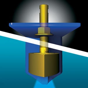
Bronze thru-hull transducer with fairing block that streamlines the outside part and corrects for the deadrise of the hull.
Threaded bronze, nylon or stainless steel shaft passes through a hole in the bottom of the hull. Choice of styles: external football-shaped head with water flow smoothed by a fairing block that also corrects for the deadrise (sideways slope of the hull); or round mushroom head thru-hulls, either semi-flush or flush mounted. Most challenging to install, but likely to provide best signal quality. Displacement, power and sailboats generally use thru-hulls. If you are considering installing a thru-hull on your boat, check out our West Advisor article on Installing a Thru-hull Transducer.
Tilted Element Transducers
A type of semi-flush thru-hull transducer. The ceramic elements are tilted inside the housing, which compensates for the boat’s deadrise. This aims the beam straight toward the bottom, resulting in stronger echo returns and more accurate depth readings. They’re a good choice for large, trailered center console and walk-around cuddy cabin powerboats that cannot accommodate a thru-hulls with fairing blocks. They provide virtually flush installation to the hull. For hull deadrise angles up to 25 degrees. Excellent high-speed results over 30 knots.
Transom Mount Transducers
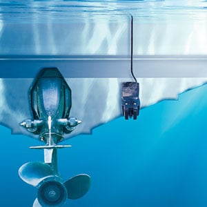
Plastic transom mount transducer in typical mounting location, on the right side of the propeller.
An adjustable-angle bracket is screwed or bolted to the transom, with the transducer hanging below and behind the hull. Simpler installation, but may encounter more turbulent water flow. Versatile and popular for trailerables. Can be used on wood, fiberglass, aluminum or steel hulls, with single or twin I/O, outboard and jet drive propulsion systems. Moderate performance at speed.
Transom-mount transducers are usually mounted to starboard because this is typically the side where the propeller blades are moving downward. The upwash from the propeller blades causes bubbles and turbulence. Mount at least 3" (75mm) beyond the swing radius of the propeller. For twin outboard or sterndrive applications, mount the transducer between the two drives, either on or just off of the centerline. Mount so that the front of the sensor is slightly higher than the back of the sensor and the sensor projects below the hull, otherwise, aeration will occur.
In-Hull Transducers
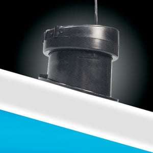
In-hull transducers can transmit and receive through the hull. No holes or external objects to snag on a trailer.
Installed against the inside of the hull bottom, the in-hull transducer sends its signal through the hull. “Shoot through hull” transducers do not need direct water contact. They’re glued to the inside of the hull with silicone or epoxy. An in-hull transducer is a good choice for a trailered boat, a vessel with a stepped hull, and for other types of high-performance hull designs, as there is no drag, hull penetration or potential for fouling. No integrated temperature sensor. Can be installed while the boat is in the water. For deadrise angles up to 30 degrees. As with thru-hulls, the selected location should be aft and close to the centerline so that the transducer is below the water line at all times.
In-hull transducers need solid fiberglass at the mounting location; no foam or plywood coring material, or air pockets. A typical 600W transducer can transmit through 1/2" to 5/8" (12mm to 16mm) of fiberglass. To install inside a cored hull, find a location with no coring or remove the core material.
According to the folks at Airmar, who manufacture the vast majority of transducers, in-hull transducers are far more sensitive than mounting a standard transducer inside your hull and perform as well as or better than comparable transducers installed outside the hull. They’re engineered to offset the signal-loss from passing through fiberglass, with built-in deadrise correction to aim the transducer’s beam straight down toward the bottom.
Trolling Motor Transducers
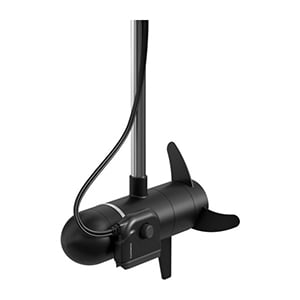
Garmin's Panoptix™ PS22-TR trolling motor transducer can be mounted to the barrel or shaft of a trolling motor to provide either LiveVü forward or down sonar.
Clamped to the outside or permanently installed inside the propeller hub of the trolling motor. A new product from Lowrance, the SpotlightScan™, clamps to your bow-mount, cable-steered trolling motor and lets you see picture-like images at 455/800kHz. You aim the transducer with your trolling motor’s remote pedal, and it has a horizontal range of about 150'. Garmin’s Panoptix PS31 Forward Transducer is a similar product, attaching to a trolling motor’s shaft, with a 417kHz beam that’s steerable both mechanically and electronically.
Transducer Materials
- Plastic thru-hull housings should not be used on a wooden boat. Wood swells as it absorbs water, so it may crack the housing.
- Bronze thru-hull housings should not be used in aluminum boats. The interaction between the aluminum and the bronze, especially in the presence of saltwater, will eat away the aluminum hull and/or bronze housing.
Available Sonar Technologies
Anglers have a baffling choice of different technologies available today. Here are the basics:
Traditional, Fixed Frequency Sonar
Traditional sonar with fixed frequencies has not changed a lot. Digitally-processed images, sometimes called Broadband technology, have cleaned things up. You can still get 50kHz, 200kHz and other fixed frequencies. For maximum depth, use lower frequencies. For the greatest resolution, the least background noise on your screen, or the best view from a fast-moving boat, use higher frequencies. If you’re using a traditional, single fixed frequency Broadband or digital sonar, we recommend 200kHz for water depths up to 200' and 80kHz or 50kHz for deeper waters. Dual frequency sonars combine low-frequency/high-frequency and wide/narrow beam operation to give anglers the advantages of both.
High-Frequency Scanning Sonar
High-frequency scanning sonars like Garmin DownVü and Lowrance StructureScan HD allow you to scan an area with a very high-frequency signal, producing picture-like images. Choose between 455kHz for scanning great ranges, and 800kHz for close-in, higher resolution detail. Raymarine CHIRP SideVision™, Garmin SideVü and Lowrance StructureScan HD allow you to search to the left and right of your boat, in addition to looking straight down.
Directional Sonar
These are sonars you can aim like the beam of a flashlight, either mechanically, because they’re attached to your trolling motor, or electronically. Garmin Panoptix, Simrad/B&G ForwardScan and Lowrance SpotlightScan are boater-controlled high-frequency directional sonars that allow you to scan an area you are interested in fishing while on approach. There are a variety of beam shapes and frequencies. An angler can view productive fish-holding spots, such as drop-offs, channels, and underwater structures, before positioning a boat on top of them making it easier to find and cast to fish. SpotlightScan and Panoptix have forward-looking versions that mount to a trolling motor. There are also side-scanning sonars that show what’s on both sides of your boat.
CHIRP sends a continuous sweep of frequencies ranging from low to high. CHIRP sonar technology then interprets frequencies individually upon their return. Since this continuous sweep of frequencies provides CHIRP with a much wider range of information, CHIRP sonar is able to create a much clearer, higher resolution image.
CHIRP Sonar
CHIRP sonar is cutting edge fishfinder technology. Unlike the single frequency of the broadband or digital sonar technology, CHIRP continuously sweeps a spectrum of many frequencies within a long duration pulse. The equivalent sound energy is hundreds of times greater than a fixed, single-frequency pulse, resulting in more energy on target. This provides huge advantages in detail, resolution and accuracy at much greater depths. Sweeping frequencies improves the quality of the sonar signal by offering:
- Better target separation: Because CHIRP uses a range of frequencies, rather than a single pulse, CHIRP sonar greatly improves the ability to distinguish fish targets that are very close together or on the bottom. Fish become easier to differentiate from the structure they are holding to.
- Less interference from errant noise that would have been picked up by a single frequency sonar. CHIRP creates a unique range of frequencies and listens for only those sonar returns; this gives CHIRP sonar the ability to distinguish between what is a real echo, and what is just extra disturbances bouncing around underwater.
Sonar Frequency Choices
Here is a quick breakdown of some options in the new world that includes high-frequency and CHIRP sonar.
- Low CHIRP (25-80kHz) or 50kHz: Lower frequency means maximum depth penetration for deep-water fishing. For greatest depth with a traditional 50kHz transducer, choose a sounder with 1-2kW of power.
- Medium CHIRP (80-160kHz) or 83kHz: Gives the widest coverage area, 83kHz is ideal for watching a bait under the transducer in shallow water.
- High CHIRP (160-800kHz) or 200kHz: Higher frequencies display a higher resolution image, making it easy to discern fish from structure or structure from the bottom. The tradeoff is that maximum depth goes down as the frequency goes up.
- 455kHz allows for scanning of a wide field of view with picture-like detail.
- 800kHz has a shallower maximum depth range but even greater realism and detail than 455kHz.
Beamwidth

Low frequencies typically have wider beam angles than high frequencies.
Lower frequency transducers generally send and receive over a wider cone angle so they cover a wider area, detect fish that aren't directly under your boat, penetrate deeper water, but don't show as much target separation. Adjacent objects may blend together and you see a blob, instead of a pair of fish. Anglers use low frequencies to keep track of a spread of multiple downriggers. Showing both frequencies on split-screen provides wide coverage plus enhanced detail.
Transmitting Power
The strength of the "ping" is expressed in watts RMS (root mean squared). Power is directly related to how well you see in silt-laden water, view down to greater depths, and successfully resolve separate targets and bottom structure. More power is better, so some manufacturers juice up the numbers by rating their product using peak-to-peak watts, which is eight times the RMS number. To avoid mixing apples and oranges, we use watts RMS exclusively.
Water Depth
If you operate in shallow waters, bottom detail and a wide beamwidth may be your highest priority. You’ll want high frequencies (200kHz, 455kHz or 800kHz). Along coasts or in deep mountain lakes, maximum water depth readings may be what you're after. For maximum depths, you want a powerful low-frequency transmitter and a narrow beam angle. Maximum depth readings will be 25–50 percent less in salt water than in fresh water.
Browse All Marine Electronics & Navigation Gear
- Chartplotters, GPS units, radar systems, and integrated navigation displays
- Sonar, CHIRP, downscan, and fish-finding electronics
- Marine stereos, speakers, amplifiers, and audio accessories
- VHF radios, AIS, satellite communication equipment
- Autopilot systems and steering control components
- Wind, depth, speed, and multifunction instruments
- Marine binoculars for navigation and low-light use
- Thermal and night-vision devices for situational awareness
- Onboard monitoring and security systems
- Magnetic and electronic compasses
- Paper and electronic navigation charts
- Regional cruising and harbor guides
- Traditional navigation plotting tools