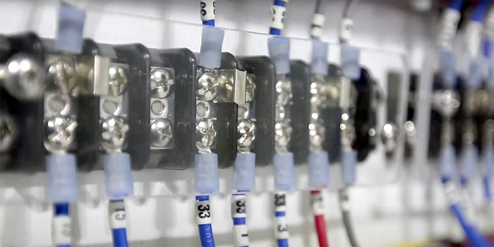
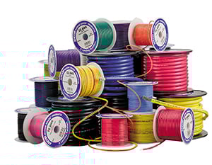
Marine grade wire is manufactured in multiple gauges for different applications. Use the charts below to determine the correct wire gauge, based on the amount of current in the circuit and the length of the wire run.
Even the experts have to check occasionally on the correct gauge and ampacity (maximum amount of electrical current a conductor can carry) of wire for a given marine DC load. The simplest method we’ve found uses the charts below. Before you use them, a few minutes spent understanding what voltage drop is, why it matters, and how these tables are structured will make you a more confident and accurate user of this reference.
Why Wire Gauge Matters: Understanding Voltage Drop
Every length of wire has electrical resistance. Current flowing through that resistance loses voltage — the longer the wire, the smaller the gauge, and the higher the current, the more voltage is lost before it reaches the device at the end of the circuit. This loss is called voltage drop, and it has real consequences for every device on your boat.
A running light rated for 12V that receives only 11.4V (a 5% drop) will be noticeably dimmer. An electronic chartplotter that receives 11V instead of 12V may perform erratically, reboot unexpectedly, or fail to operate at all. A VHF radio operating below its rated voltage may transmit at reduced power. A bilge pump receiving low voltage may run but not develop full flow rate — exactly when you need it most. These are not theoretical concerns: undersized wire on a long run is one of the most common causes of intermittent electronics problems on boats, and most boaters never identify it as the source.
The ABYC establishes two voltage drop standards for marine DC wiring:
- 3% maximum for critical circuits: panelboard or switchboard feeders, bilge blowers, electronic equipment, and navigation lights. On a 12V system, 3% equals 0.36V — meaning the device at the end of the circuit must receive at least 11.64V.
- 10% maximum for non-critical circuits: cabin lighting other than navigation lights, and other loads where voltage drop is not critical.
The voltage drop equation is: Voltage Drop = Current × Length × Ohms per foot
This equation lets you calculate the drop for any circuit if you know the wire’s resistance per foot — which is listed in the AWG Wire Specs table at the bottom of this page. The tables below do this calculation for you across the most common combinations of current and circuit length.
How to Use These Tables Correctly
Round-trip length is not the same as one-way distance. This is the most common mistake when using voltage drop tables. Current flows from the battery or panel to the load through the positive wire, and returns from the load to the battery through the negative wire. Both wires have resistance and both cause voltage drop. The “Length” column in these tables is the total round-trip distance — from the panel or battery to the load and back. If your device is 15 feet from the panel, the circuit length for table use is 30 feet, not 15. Underestimating circuit length leads to selecting wire that is too small, producing more voltage drop than intended.
The AWG numbering system runs backward from what you might expect. Larger AWG numbers indicate smaller, thinner wire. AWG 18 is the thinnest wire in these tables; AWG 4/0 is the largest and heaviest. A larger (thicker) wire has lower resistance, carries more current, and produces less voltage drop per foot. When in doubt, the next gauge up — a lower AWG number — is always the safer choice.
How to read the tables:
- Select either the 3% or 10% table based on the type of circuit.
- Find the current consumption of your load on the horizontal axis.
- Find the round-trip circuit length on the vertical axis.
- The wire gauge at the intersection is the minimum correct gauge for that combination.
Worked example — navigation light: A running light draws 2A. Your boat is 20 feet long, so the round-trip distance from the panel to the forward light and back is approximately 40 feet. Navigation lights are critical circuits requiring the 3% table. Find 5A (the next column at or above 2A) across the top, and 40 feet down the left side. The intersection shows AWG 10. Use AWG 10 for that circuit.
Worked example — cabin fan: A cabin fan draws 0.5A. The round-trip run from the panel is 30 feet. Cabin lighting is a non-critical circuit using the 10% table. Find 5A across the top and 30 feet on the left. The intersection shows AWG 18 — the smallest wire in the table, which is adequate for this low-current, short-run application.
Understanding the Chart Assumptions
The tables are built on four assumptions. If any of these do not apply to your installation, you must adjust the result:
- 105°C insulation rating: All Ancor wire uses 105°C insulation rating. Wire with lower-rated insulation cannot safely carry as much current at the same gauge. If you are using wire with a lower insulation temperature rating, derate the ampacity accordingly. This is another reason to use marine-grade wire rather than automotive or household wire — lower-rated insulation limits the current the wire can carry safely.
- AWG wire sizes, not SAE: All Ancor wire uses AWG wire sizes. SAE wire sizes are 6 to 12 percent smaller in cross-section than the same nominal AWG gauge, carry proportionally less current, and have greater resistance per foot. The wire charts in Chapman’s Piloting and other marine publications are for AWG wire. If you are using SAE wire, the tables will overestimate its capability — another reason to use marine-grade AWG wire from the start.
- Wires are not run in engine spaces: Engine compartments are typically 20°C hotter than the rest of the boat (50°C vs. 30°C). Higher ambient temperature reduces a wire’s ability to dissipate heat, which reduces safe ampacity. For wires routed through engine spaces, reduce the maximum current capacity from the table by 15 percent. For example, a wire rated at 60A from the table should be treated as a 51A wire (60 × 0.85) in an engine compartment.
- Conductors are not bundled: When multiple wires are bundled together, they cannot dissipate heat as effectively as individual wires, reducing safe ampacity. Apply these derating factors if your wires run bundled: three conductors bundled — reduce maximum amperage by 30%; four to six conductors bundled — reduce by 40%; seven to 24 conductors bundled — reduce by 50%. A wiring harness containing eight conductors means every wire in that bundle must be derated to 50% of its individual ampacity from the table.
Note on 24V Systems
These tables are calculated for 12V DC systems only. For 24V systems, the same absolute voltage drop produces a smaller percentage drop relative to system voltage, which means you can use the 10% table where you would otherwise use the 3% table, or you may be able to use a smaller wire gauge for the same combination of current and circuit length. The simplest approach for 24V systems is to use Blue Sea Systems’ online Circuit Wizard, which performs the calculation for any system voltage.
3% Voltage Drop
Use 3% voltage drop for critical applications affecting the safety of your boat and crew, such as running lights, blowers, electronics and panel board feeds. Remember that the Length is a round-trip distance. This table is for 12-Volt systems only.
| Current (Amps) → | |||||||||||||
|---|---|---|---|---|---|---|---|---|---|---|---|---|---|
| Length ↓ | 5A | 10A | 15A | 20A | 25A | 30A | 40A | 50A | 60A | 70A | 80A | 90A | 100A |
| 10' (3m) | 18 | 14 | 12 | 10 | 10 | 8 | 6 | 6 | 6 | 6 | 6 | 4 | 4 |
| 15' (5m) | 16 | 12 | 10 | 10 | 8 | 8 | 6 | 6 | 4 | 4 | 4 | 2 | 2 |
| 20' (6m) | 14 | 10 | 10 | 8 | 6 | 6 | 6 | 4 | 4 | 2 | 2 | 2 | 2 |
| 25' (8m) | 12 | 10 | 8 | 6 | 6 | 6 | 4 | 4 | 2 | 2 | 2 | 1 | 1 |
| 30' (9m) | 12 | 10 | 8 | 6 | 4 | 4 | 4 | 2 | 2 | 2 | 2 | 1 | 1 |
| 40' (12m) | 10 | 8 | 6 | 6 | 4 | 4 | 2 | 2 | 1 | 1/0 | 1/0 | 2/0 | 2/0 |
| 50' (15m) | 10 | 6 | 6 | 4 | 4 | 2 | 2 | 1 | 1/0 | 2/0 | 3/0 | 4/0 | 4/0 |
| 60' (18m) | 10 | 6 | 6 | 4 | 2 | 2 | 1 | 1/0 | 2/0 | 3/0 | 3/0 | 4/0 | 4/0 |
| 70' (21m) | 8 | 6 | 4 | 2 | 2 | 1 | 1/0 | 2/0 | 3/0 | 3/0 | 4/0 | 4/0 | |
| 80' (24m) | 8 | 6 | 4 | 2 | 2 | 1 | 1/0 | 2/0 | 3/0 | 4/0 | 4/0 | ||
| 90' (27m) | 8 | 4 | 2 | 2 | 1 | 1/0 | 2/0 | 3/0 | 4/0 | 4/0 | |||
| 100' (30m) | 6 | 4 | 2 | 2 | 1 | 1/0 | 2/0 | 3/0 | 4/0 | ||||
| 110' (33m) | 6 | 4 | 2 | 2 | 1 | 1/0 | 2/0 | 3/0 | 4/0 | ||||
| 120' (36m) | 6 | 4 | 2 | 1 | 1/0 | 2/0 | 3/0 | 4/0 | |||||
| 130' (40m) | 6 | 2 | 2 | 1 | 1/0 | 2/0 | 3/0 | 4/0 | |||||
| 140' (43m) | 6 | 2 | 2 | 1/0 | 2/0 | 3/0 | 4/0 | ||||||
| 150' (46m) | 6 | 2 | 1 | 1/0 | 2/0 | 3/0 | 4/0 | ||||||
| 160' (49m) | 6 | 2 | 1 | 1/0 | 2/0 | 3/0 | 4/0 | ||||||
| 170' (52m) | 6 | 2 | 1 | 2/0 | 3/0 | 4/0 | 4/0 |
10% Voltage Drop
Use 10% voltage drop for non-critical applications such as windlass, cabin lights, circuits other than running lights, electronics or panel board feeds. Remember that the Length is a round-trip distance. This table is for 12-Volt systems only.
| Current (Amps) → | |||||||||||||
|---|---|---|---|---|---|---|---|---|---|---|---|---|---|
| Length ↓ | 5A | 10A | 15A | 20A | 25A | 30A | 40A | 50A | 60A | 70A | 80A | 90A | 100A |
| 10' (3m) | 18 | 18 | 18 | 16 | 16 | 14 | 14 | 12 | 10 | 10 | 10 | 10 | 10 |
| 15' (5m) | 18 | 18 | 16 | 14 | 14 | 12 | 12 | 10 | 10 | 8 | 8 | 8 | 8 |
| 20' (6m) | 18 | 16 | 14 | 14 | 12 | 12 | 10 | 10 | 8 | 8 | 8 | 6 | 6 |
| 25' (8m) | 18 | 16 | 14 | 12 | 12 | 10 | 10 | 8 | 8 | 6 | 6 | 6 | 6 |
| 30' (9m) | 18 | 14 | 12 | 12 | 10 | 10 | 8 | 8 | 6 | 6 | 6 | 6 | 4 |
| 40' (12m) | 16 | 14 | 12 | 10 | 10 | 8 | 8 | 6 | 6 | 6 | 4 | 4 | 4 |
| 50' (15m) | 16 | 12 | 10 | 10 | 8 | 8 | 6 | 6 | 4 | 4 | 4 | 2 | 2 |
| 60' (18m) | 14 | 12 | 10 | 8 | 8 | 6 | 6 | 6 | 4 | 4 | 4 | 2 | 2 |
| 70' (21m) | 14 | 10 | 8 | 8 | 6 | 6 | 6 | 4 | 2 | 2 | 2 | 2 | 1 |
| 80' (24m) | 14 | 10 | 8 | 8 | 6 | 6 | 4 | 4 | 2 | 2 | 2 | 1 | 1 |
| 90' (27m) | 12 | 10 | 8 | 6 | 6 | 6 | 4 | 2 | 2 | 2 | 1 | 1 | 1/0 |
| 100' (30m) | 12 | 10 | 8 | 6 | 6 | 4 | 4 | 2 | 2 | 1 | 1 | 1/0 | 1/0 |
| 110' (33m) | 12 | 8 | 8 | 6 | 6 | 4 | 2 | 2 | 2 | 1 | 1/0 | 1/0 | 1/0 |
| 120' (36m) | 12 | 8 | 6 | 6 | 4 | 4 | 2 | 2 | 1 | 1 | 1/0 | 1/0 | 2/0 |
| 130' (40m) | 12 | 8 | 6 | 6 | 4 | 4 | 2 | 2 | 1 | 1/0 | 1/0 | 2/0 | 2/0 |
| 140' (43m) | 10 | 8 | 6 | 6 | 4 | 2 | 2 | 1 | 1 | 1/0 | 2/0 | 2/0 | 2/0 |
| 150' (46m) | 10 | 8 | 6 | 4 | 4 | 2 | 2 | 1 | 1/0 | 1/0 | 2/0 | 2/0 | 3/0 |
| 160' (49m) | 10 | 8 | 6 | 4 | 4 | 2 | 2 | 1 | 1/0 | 2/0 | 2/0 | 3/0 | 3/0 |
| 170' (52m) | 10 | 6 | 6 | 4 | 2 | 2 | 2 | 1 | 1/0 | 2/0 | 2/0 | 3/0 | 3/0 |
To Complete Your Project, Don't Forget:
AWG Wire Specs
| Wire Size (AWG) | Nominal OD | Weight per 1000' | Stranding Number of 30 AWG | Cir.Mil. Area | Square mm | Ohms per 1000' | Max Amps |
|---|---|---|---|---|---|---|---|
| 18 | 7/64" | 12lb. | 16 | 1,600 | 0.823 | 6.48 | 20 |
| 16 | 1/8" | 16lb. | 26 | 2,600 | 1.31 | 4.00 | 25 |
| 14 | 9/64" | 23lb. | 41 | 4,100 | 2.08 | 2.50 | 35 |
| 12 | 5/32" | 31lb. | 65 | 6,500 | 3.31 | 1.75 | 45 |
| 10 | 7/32" | 44lb. | 105 | 10,500 | 5.26 | 0.98 | 60 |
| 8 | 5/16" | 86lb. | 168 | 16,800 | 8.37 | 0.62 | 80 |
| 6 | 11/32" | 118lb. | 266 | 26,600 | 13.30 | 0.40 | 120 |
| 4 | 13/32" | 178lb. | 420 | 42,000 | 21.15 | 0.24 | 160 |
| 2 | 15/32" | 277lb. | 665 | 66,500 | 33.62 | 0.157 | 210 |
| 1 | 17/32" | 350lb. | 836 | 83,690 | 44.21 | 0.127 | 245 |
| 1/0 | 9/16" | 437lb. | 1064 | 105,600 | 53.49 | 0.099 | 285 |
| 2/0 | 5/8" | 549lb. | 1330 | 133,000 | 67.43 | 0.077 | 330 |
| 3/0 | 11/16" | 675lb. | 1665 | 167,800 | 85.01 | 0.062 | 385 |
| 4/0 | 13/16" | 837lb. | 2109 | 211,600 | 107.20 | 0.049 | 445 |
Frequently Asked Questions: Marine Wire Gauge and Voltage Drop
How do I find the correct wire gauge for my boat?
Determine two things: the current draw of the device in amps, and the round-trip wire length from your panel or battery to the device and back. Then choose either the 3% or 10% voltage drop table based on whether the circuit is critical (navigation lights, electronics, blowers — use 3%) or non-critical (cabin lighting, non-safety loads — use 10%). Find the current in the top row and the round-trip length in the left column. The gauge at the intersection is the minimum correct wire size for that combination.
Why does the table use round-trip length, not one-way distance?
Both the positive and negative conductors carry current and both have resistance, so both contribute to total voltage drop. A device 15 feet from the panel has a 30-foot round-trip circuit. Using one-way distance would underestimate the total resistance by half, leading to wire that is too small and more voltage drop than the 3% or 10% limit — potentially enough to affect device performance.
What is the difference between AWG and SAE wire, and does it matter?
AWG (American Wire Gauge) is the standard used for marine-grade boat cable. SAE wire — the type used in automotive applications — uses the same gauge numbers but has a smaller actual cross-section, 6 to 12% smaller than the equivalent AWG size. This means SAE wire has higher resistance per foot and lower ampacity than AWG wire at the same nominal gauge. The voltage drop tables on this page are calculated for AWG wire. Using SAE wire with these tables will produce a wire that is undersized for the intended application. Marine-grade AWG wire from Ancor or equivalent manufacturers is the correct choice for all boat wiring.
What happens if I use wire that is too small?
Undersized wire causes voltage drop that reduces device performance — dimmer lights, erratic electronics, reduced pump flow rates. More seriously, undersized wire generates heat under load. Enough heat can degrade insulation, melt wire jackets, and start fires. ABYC standards for marine wiring are designed to prevent both performance problems and fire hazards. Always use the minimum gauge from the table or larger — never smaller.
Do I need to adjust the wire gauge for wires in the engine compartment?
Yes. Engine compartments are typically 20°C hotter than the rest of the boat, which reduces a wire’s ability to dissipate heat and lowers its safe ampacity. For any wire routed through an engine space, reduce the maximum amperage from the table by 15 percent. Select a wire size whose table ampacity, after applying the 15% derating, is still above your circuit’s actual load current.
Can I use these tables for a 24V system?
The tables are calculated for 12V DC systems only. For 24V systems, voltage drop as a percentage of system voltage is half that of a 12V system for the same wire size and current. You can use Blue Sea Systems’ Circuit Wizard, which calculates correct wire gauge for any system voltage, or consult the ABYC tables directly for 24V system wiring.