There’s an old axiom that states, “The strongest chain is only as reliable as its weakest link.”
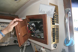
Behind these gold-colored switch panels lurked a 40-year-old tangle of do-it-yourself wiring projects. The amazing thing is that all of the systems still worked. Does your boat have a similar legacy of bad electrical work?
That same truism can be applied to your boat’s DC electrical system. Put it in a corrosive environment, where wiring and electrical components are subjected to more concentrated daily abuse than your family car will experience in five years, and it’s easy to see how small electrical problems can get out of hand very quickly.
Safety onboard begins with a reliable DC electrical system, properly installed with quality wiring, connections and components. Don’t take shortcuts when wiring your boat, or you may compromise the safety of your boat and crew. This is critically important because, according to BoatUS Marine Insurance, problems with DC electrical systems are responsible for 32 percent of onboard fires, more than any other category of causes.
In my several decades of owning and working on boats, I have personally seen more examples of scary do-it-yourself DC electrical projects than any other type of boat equipment disaster. Something about 12-volt DC power seduces and encourages hack electricians to try their hand using household-grade wire and terminals. The amazing thing is how many of these rat’s nests of wiring actually work, for the moment.
If you’re not familiar with basic electrical practices and theory, hire someone who is, and let them install that new fishfinder, LED cabin light, anchor windlass or subwoofer! With that said, there are a lot of great resources that you can purchase from your favorite book store, like Don Casey’s Sailboat Electrical Systems: Improvement, Wiring, and Repair, John C. Payne’s Marine Electrical Bible and Edgar J. Beyn’s The 12-Volt Doctor's Practical Handbook, so you really can learn to complete some simple electrical projects on your boat. This stuff really is not rocket science.
This West Advisor will help you understand some basic standards and practices of DC marine wiring. We’ll start with one of the most frequently asked questions—which kind of wire to use.
Can I use “regular wire” for my boat?
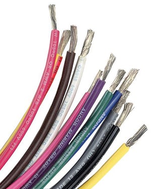
Ancor marine-grade wire products are the longest lasting and most rugged available, exceeding UL 1426, ABYC and US Coast Guard Charter boat (CFR Title 46) standards. Notice the silver color of the conductors, because the wire is “tinned.”
The answer to this common question is a qualified “yes,” if the wire is SAE (Society of Automotive Engineering) J378, J1127 or J1128. These wires are designed for “surface vehicles,” not for the special requirements of the marine industry, but meet the minimum standards for boats in limited circumstances.
Even if tinned copper, your wiring should not be run in bilge spaces or other areas subject to moisture from spray or dripping. American Boat and Yacht Council (ABYC) standards include this requirement: “Current-carrying conductors shall be routed as high as practicable above the bilge water level and other areas where water may accumulate. If conductors must be routed in the bilge or other areas where water may accumulate, the connections shall be watertight (11.14.4.1.5 ).” They should not be run in engines spaces, unless marked “oil resistant” and “75°C”. They should not be used in applications where subjected to vibration or frequent flexing and must never be used for 110 volt applications. For safety, use only wire that is marked with size and type.
Most importantly, SAE wire is up to 12 percent smaller than American Wire Gauge (AWG) Boat Cable which means that, in many applications, larger gauge wire must be used to stay within the voltage drop limits recommended by experts (see our West Advisor Marine Wire Size and Ampacity). The wire charts found in Chapman’s Piloting and other publications are all for AWG wire like that made by our supplier, Ancor, not SAE type wire. In general, wiring on boats should be of the stranded type, not solid copper wire used in household applications, which does not withstand the vibration found onboard a boat.
With that said, why not just use real marine grade wire?
Primary Wire Color Standards
The ABYC (American Boat and Yacht Council) Standards & Technical Information Reports for Small Craft recommends the following color standards for marine wiring of boat engines and accessories. Select wire color from the list below.

What size wire should I use?
This is a basic question you need to tackle when designing your own wiring. Installing overly large wire is expensive and adds weight, but installing wire of inadequate size is a safety concern. There are four key variables you should consider: amperage or ampacity, temperature, whether the wires are bundled closely together, and voltage drop.
Ampacity
Ampacity is defined as the current carrying capacity of a conductor or device—how many amperes of current you can run through it. Many electrical loads, such as LED lights, for example, draw a constant amount of amps so are simple to calculate by checking the specs of the device. Others, such as power inverters or any device operating an electrical motor, will have a large spike in amperage when they start operating. Your circuit needs to be sized to handle all of the maximum amperages of all the devices in the circuit. If you’re installing an anchor windlass that typically draws 80 amps, but may draw 300 amps when you’re trying to break your anchor loose from a rocky bottom, you need to size the wiring accordingly.
Temperature
The temperature where you are running your wiring affects how much current it can safely carry. Briefly, the higher the ambient temperature of the environment, the lower the amount of amperage the cable can carry. If you’re running wiring through your boat’s engine room, ABYC standards assume the temperature is 122°F (50°C). If you’re planning a circuit with #6 AWG wire size, it can safely carry 80 amps outside the engine room, but only 46.4 amps in the hotter engine room environment. In general, maximum current is 15 percent less in engine spaces, which are assumed to be 20°C hotter than non-engine spaces (50°C vs. 30°C).
Cable Bundling
While we’re on the topic of heat, you should understand that cables that are bundled together generate a cumulative amount of heat, and have more difficulty dissipating that heat than when they are run individually. This is something to be aware of, but the relevant ABYC standard only applies to wiring carrying 50 volts or more, so it is typically a problem with AC circuits on a boat, not your typical 12 volt DC wiring installation. In general, if three conductors are bundled, reduce maximum amperage by 30 percent. If four to six conductors are bundled, reduce maximum amperage by 40 percent. If seven to 24 conductors are bundled, reduce amperage by 50 percent.
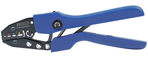
Ancor Double Crimp Ratcheting Wire Terminal Crimper
Voltage Drop
Voltage drop, our fourth key variable in wire sizing, introduces the factor of the length of the wires into your calculations. Each wire has a predictable level of internal resistance, so that in a DC circuit, you will lose a certain amount of energy that’s turned into heat. The longer the wiring run, the greater the voltage drop. This can be a real problem with some types of electronics or with electric motors, which will run more slowly at 11.5 volts.
The solution is to use a wire with lower internal resistance—a larger diameter wire, since bigger wires have less resistance—and ABYC gives us a choice of two voltage drop tables to calculate this size. We have shared both of these voltage drop tables in our West Advisor, Marine Wire Size and Ampacity. The ABYC’s standards for voltage drop read as follows: “Conductors used for panelboard or switchboard (main) feeders, bilge blowers, electronic equipment, navigation lights, and other circuits where voltage drop must be kept to a minimum, shall be sized for a voltage drop not to exceed three percent. Conductors used for lighting, other than navigation lights, and other circuits where voltage drop is not critical, shall be sized for a voltage drop not to exceed 10 percent.”
I don’t know about you, but on my boat, I don’t want any of my 12 volt devices running at a voltage that’s 1.2 volts (10 percent of 12 volts) less than what it’s designed for! Nigel Calder agrees with this viewpoint in his Boatowner’s Mechanical and Electrical Manual, one of the key books you should have on your shelf if you own a boat. He writes, “I recommend always using the three percent table, given the harshness of the marine environment, it just does not pay to start out by trying to cut calculations as fine as possible.” So, if you take our advice—and Calder’s—just use the three percent voltage drop numbers. This makes sizing wire much easier, because if you make your wiring large enough to prevent a drop in voltage, you’ll have cables that will easily meet the ampacity requirements.
Making Secure Connections
Are soldering or crimping terminals better?
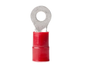
Nylon 8 AWG Red Ring Terminal
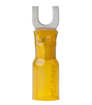
12-10 #10 Heat Shrink Spade Terminal
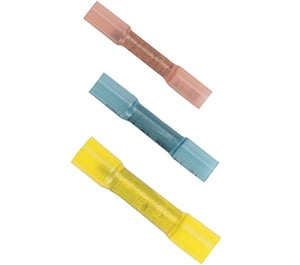
Heat Shrink Butt Connectors, 22-18 gauge red, 16-14 gauge blue, 12-10 gauge yellow
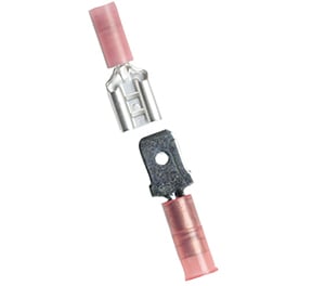
Red male and female nylon disconnects, 22-18 gauge
Red Heat Shrink Snap Plugs, 22-18 gauge
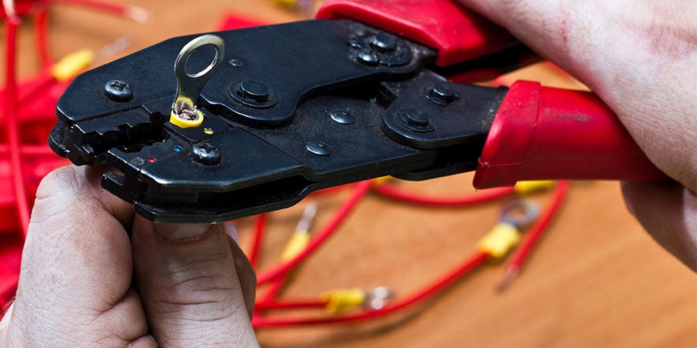
Most wire problems happen at the connections, and the experts are mostly in agreement on this one. Connections should be mechanically connected, not just soldered. Per ABYC (E-11.16.3.7), “Solder shall not be the sole means of mechanical connection in any circuit”. Further, crimping provides a solid mechanical connection resistant to “cold joints” breaking under fatigue, and removes strain.
NEVER twist wires together, connect wires together with household “wire nuts” or wrap a bare wire around a terminal screw to connect wires together. A proper crimp connection is essential for safety and current-carrying ability. Use a good quality crimper, like the Ancor Double Crimp Ratcheting Wire Terminal Crimper. The ABYC Standards (11.14.3.8) have something to say about this too, advising that “Solderless crimp on connectors shall be attached with the type of crimping tools designed for the connector used, and that will produce a connection meeting the requirements of E-11.14.3.3.” That means they recommend you use a crimper made by Ancor if you’re crimping Ancor-made terminals, because the barrel and insulation thicknesses vary from one manufacturer to another.
Use the Pull Test
Put the terminals in the correct die in the crimper, insert the wire into the terminal, and squeeze until the jaws grip the terminal lightly and hold it in place without distortion. Check the finished crimp to see that the wire is firmly in place by giving it a good solid tug. By the way, 16 Gauge AWG connectors are designed to safely handle a pull of 15 pounds; 10 Gauge terminals are rated for 40 pounds; 00 battery cable terminals are rated for 150 pounds, per ABYC. Finish the job with heat-activated, adhesive-lined heat shrink tubing.
Terminals are color-coded to fit different gauges of wire: red for 22- to 18-gauge wire, blue for 16- to 14-gauge wire and yellow for 12- to 10-gauge wire. Select the proper terminal for your job. Below are some examples and their uses:
Ring Terminals
For permanent secure termination. Ring terminals can’t pull off, and for that reason are preferred over spade terminals. Per ABYC E-11.14.4.1.11, “Ring and captive spade type terminal connectors shall be the same nominal size as the stud.”
Flanged Spade Terminals
For permanent termination when terminal screw is captive. ABYC recommends: “Terminal connectors shall be of the ring or captive spade types.” E-11.16.3.4
Butt Connectors
For connecting two wire leads of the same size. Step-down butt connectors join a pair of conductors to a third, all of the same size, or join two conductors of different sizes.
Disconnects and Snap Plugs
Quick-disconnect connectors, also called “disconnects,” are common as a quick connect/disconnect solution for electronic and digital equipment. The ABYC recommends their use for circuits of not more than 20 amps, with a voltage drop of less than 50 mV with a 20-amp current, and as long as they stay connected with up to a six-pound pull.
Wire Support Standard
The ABYC recommends that wires be supported every 18" along their path. This is to prevent repeated flexing, due to the boat’s motion through the water, or the engine’s vibration. Cable ties and clamps are approved methods of securing wires.
More Wiring Standards From ABYC
Extra Wire at Junction Boxes or Distribution Panels
“11.14.4.1.12 Conductors terminating at panelboards in junction boxes or fixtures shall be arranged to provide a length of conductor to relieve tension, to allow for repairs and to permit multiple conductors to be fanned at terminal studs.”
Chafe Protection
“11.14.4.1.7 Conductors that may be exposed to physical damage shall be protected by self-draining loom, conduit, tape, raceways, or other equivalent protection. Conductors passing through bulkheads or structural members shall be protected to minimize insulation damage such as chafing or pressure displacement. Conductors shall also be routed clear of sources of chafing such as steering cable and linkages, engine shafts, and control connections.”
Only Four Terminals
“11.14.4.1.10 No more than four terminals shall be secured to any one terminal stud. If additional connections are necessary, two or more terminal studs shall be connected together by means of jumpers or copper straps.” See also 11.14.4.1.10.2.1. It states that you can also swage multiple conductors into one terminal, provided that “the combined circular millimeters of the conductors does not exceed the circular millimeter capacity of the terminal“ and that you test the connection using the pull test described in E-11.14.3.3.
Install the Highest Ampacity Terminal First
If you’re installing more than one ring terminal onto a stud, the largest and therefore highest ampacity terminal should be installed first, with successively smaller and lower-ampacity terminals installed afterward (11.14.4.1.10.1). Also note 11.14.4.1.11, which states that “Ring and captive spade type terminal connectors shall be the same nominal size as the stud.”
Avoiding Magnetic Interference With a Compass
“11.14.4.2.1 Wiring shall be installed in a manner that will avoid magnetic loops in the area of the compass and magnetically sensitive devices. Wires that may create magnetic fields in this area shall run in twisted pairs.”
Ancor Heat Shrink Tubing Specs
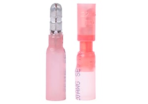
ABYC recommends: “The shanks of terminals shall be protected against accidental shorting by the use of insulation barriers or sleeves, except for those used in grounding systems.” E-11.16.3.9. Heat shrink tubing, lined with adhesive, creates water, oil and acid-resistant seal, preventing corrosion at the electrical connection. It shrinks to one-third of its original size (a 3:1 shrink ratio).
| Size | Shrinks to | Wire Range (AWG) |
|---|---|---|
| 1/8" | 1/32" | <18 |
| 3/16" | 1/16" | 20 -12 |
| 1/4" | 5/64" | 16 - 10 |
| 1/2" | 1/8" | 12 - 8 |
| 3/4" | 5/32" | 8 - 4 |
| 3/4" | 1/4" | 6 - 2/0 |
DC Circuit Wizard
Blue Sea Systems’ DC Circuit Wizard performs calculations and recommends appropriate circuit protection options—fuse or circuit breaker—and wire size for just about all DC applications.
Design rule: A change in six gauge numbers is a fourfold increase in wire size. When the wire size goes down two numbers (from 14 to 12), the amount of copper in the wire goes up by 59 percent.